Looking back to 1960, there were 600 consumer product-related electrocutions per year. Today, that number is significantly reduced with the addition of GFCI’s. Here, we’ll break down devices that prevent electric shock and take a closer look at GFCI receptacles and GFCI circuit breakers vs outlets.
What is an Outlet
According to the National Electrical Code (NEC), an outlet is defined as “a point on the wiring system at which current is taken to supply utilization equipment.”
A common mistake is interchanging outlets for receptacles. Here, we’ll clarify how receptacles differ and what their true purpose is.
What is a Receptacle
The NEC defines receptacles as “contact devices installed at the outlet for the connection of an attachment plug, or for the direct connection of electrical utilization equipment designed to mate with the corresponding contact device.”
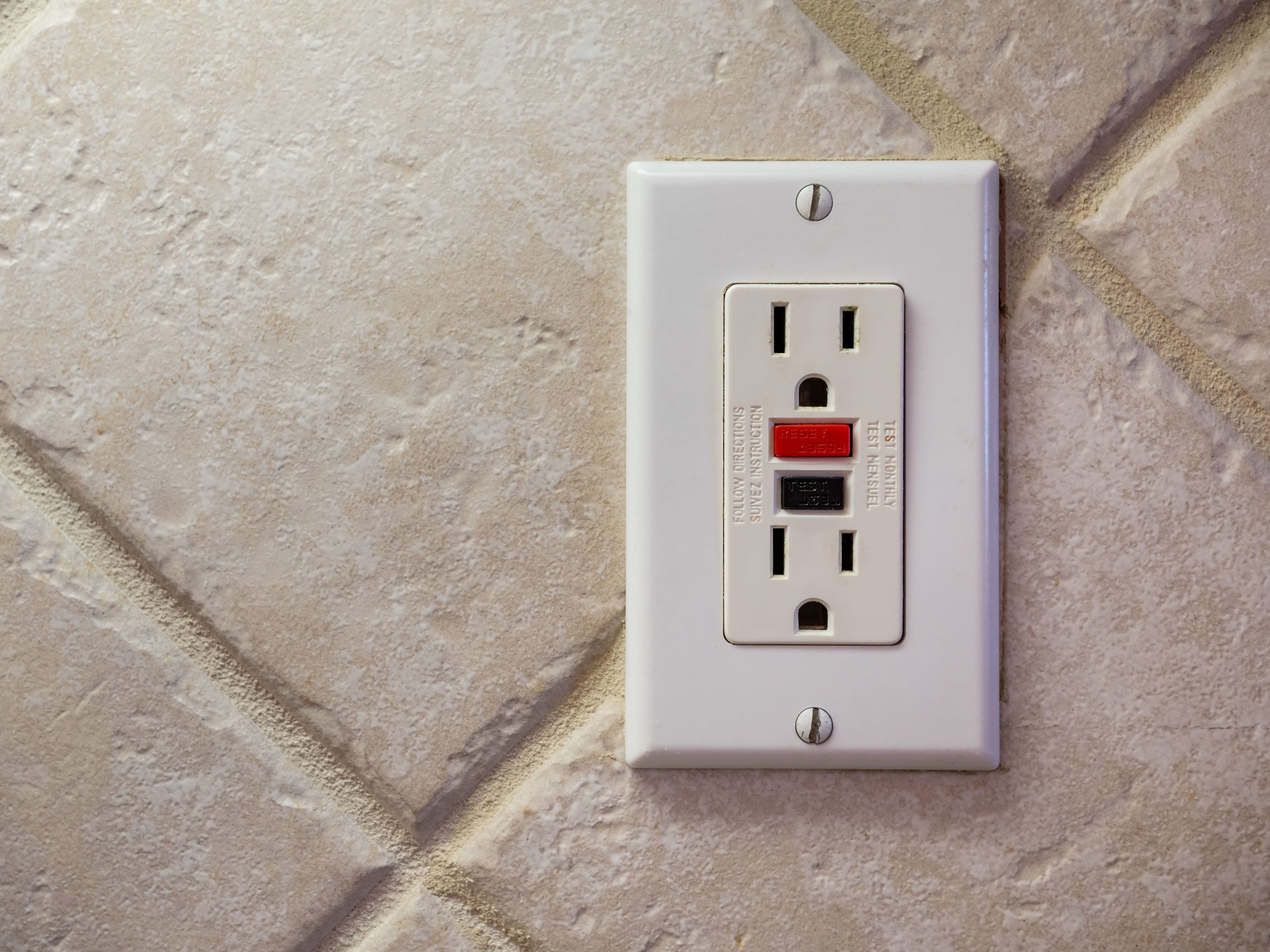
GFCI Receptacles
GFCI receptacles are installed in the living space; the indicator light reveals problems that might arise with the branch circuit, but only trip on ground fault by measuring the current going out and comparing it to the current returning to source. GFCI receptacles also have the ability to detect bootleg equipment ground (improper connection of the neutral).
Often, GFCI protection is required in wet areas that are not readily accessible, such as a dishwasher branch circuit. Manufacturers require a monthly and before use test of the trip function on the GFCI device. For this reason, Etechs must be able to distinguish between accessible and readily accessible locations.
In order to test the GFCI trip function, in the case of the dishwasher receptacle, location would be determined accessible due to the location under the countertop or behind doors. For purposes of the NEC, the correct GFCI protection device would be a GFCI circuit breaker, not a GFCI receptacle. The GFCI circuit breaker is considered readily accessible in the panelboard.
GFCI Circuit Breakers
GFCI circuit breakers are located in panelboards and are deemed readily accessible by the NEC. GFCI circuit breakers trip on short circuit, overload, arc fault and ground fault. Learn more about different Circuit Breaker Types and Functions in our blog post.
Normal Circuit Operation
Every branch circuit has a source, conductors and a load., This means:
- Current flows on the line conductor from line to the load
- Current returns from the load on the neutral
- Exactly the same amount of current flows from line to load, and returns from load to line
Ground Fault — Indirect Contact
When a person contacts the bonded enclosure with a fault, it is called “indirect contact.” The equipment grounding conductor (EGC) is effective, and current divides and flows to ground based on the impedance of the two fault paths:
- EGC has low impedance — most of the fault current flows on it
- For a person with comparatively higher impedance — a small amount of fault current flows through the person and may or may not feel a shock
Ground Fault — Direct Contact
If EGC is absent (cut off prong on plug), then all the fault current will flow through the person. This is called direct contact. The amount of current is determined by the impedance of the person. Dry hands or large person have a higher impedance than wet hands or small person.
People are frozen to a circuit at 10mA and go into fibrillation at 50mA.
OSHA’s Nationally Recognized Testing Laboratory (NRTL)
NRTL recognizes private sector organizations to perform certification for certain products to ensure that they meet the requirements of both the construction and general industry OSHA electrical standards.
UL 943 Standard applies to Class A, single-phase, three-phase, ground-fault circuit-interrupters intended for protection of personnel, for use only in grounded neutral systems.
Electricians are required to look for the UL symbol (or another NRTL symbol) on individual equipment prior to installing.
Protecting Personnel vs Equipment
The most important thing to understand is the difference between GFCI Class A devices. They are intended to protect a person against electric shock versus GFPE — another class of GFCI that is designed to protect electrical equipment.
GFPE’s have different trip levels represented by UL, in the associated UL standard and Class, for specific types of equipment protection. GFCI must provide both let-go and fibrillation protection, and a Class A device is required.
National Electrical Manufacturers Association (NEMA) conducted an evaluation of a GFCI’s actual tripping characteristics. According to their findings, a typical Class A GFCI will trip at:
- 6mA fault of .1 to .04 seconds
- ·50mA fault of less than .02 seconds
Typical Class A GFCI’s are well below the UL requirements. According to UL standard 943 for a Class A GFCI:
If the system voltage is less than 150V, and the equipment is neither bonded nor double insulated, a Class A GFCI with 4 to 6 mA trip current is required to provide both let-go protection and protection against fibrillation tripping.
- 3mA tingle sensation
- 5mA pain
- 20mA let go
- 60mA defibrillation
UL Class A GFCI Test Standards
Every GFCI must pass the following “in-line” manufacturing tests:
- No trip below 4mA (no load)
- Must trip at 6mA (no load)
- No trip below 4mA (with load)
- Must trip at 6mA (with load)
- Must trip with 2 ohm grounded neutral
- Must trip within 25 ms with a 500 ohm fault
- Must trip with “test button”
- Must not trip with “noise”
- Calibration test at 102V
- Test button at 132V
- 1500V hi-pot
Installing a GFCI Receptacle Upstream
If there is no equipment grounding conductor, such as in two-wire household products, the solution to install a GFCI receptacle is an option to provide electric shock prevention.
Step 1: Use a circuit tracer.
Step 2: A QP (qualified person) identifies the circuit transmitter at the receptacle and the receiver at the panelboard. The receiver indicates the signal at the circuit breaker, and the tech then isolates the source.
Step 3: Sure tester settings are selected and recorded at each receptacle in the circuit.
Step 4: The Etech installs the GFCI receptacle at the receptacle outlet with lowest voltage drop reading.
Pro tip: Usually it is the receptacle outlet nearest to the panelboard.
Step 5: Connect the downstream receptacles’ outlets to the load side of the GFCI receptacle.
Step 6: Using the labels provided with the GFCI receptacle, apply accordingly. For example, if the Etech has replaced a two-slot receptacle with a three-slot receptacle, the tech must apply the ungrounded label to the downstream receptacles, as well as the ground fault protected label.
Step 7: Energize the branch circuit and verify power at the GFCI receptacle. Test all GFCI protected receptacles.
For more detailed information on electrical devices you’ll likely encounter in the field and how to respond to problems with them, check out Interplay Learning’s™ Electrical Devices course.

Chad Soucy
Interplay Learning Electrical Expert
Chad is Interplay’s electrical expert and is a Master Electrician. Chad has progressed as an electrical professional throughout his career, with early beginnings in rewiring/wiring homes to QA/Commissioning plants, honing his skills in all aspects of the electrical trade along the way. He transitioned his career through Residential, Commercial and Industrial sites, and in 2012, further expanded on his mission to lifelong learning in becoming an electrical instructor. He continued on this path as an online course developer and is steadfastly committed to electrical safety and sound adult learning theories.