A multimeter is an important tool for troubleshooting and measuring the overall performance of an electrical circuit or machine. To use it correctly, it’s important to learn each of the common multimeter function settings.
Multimeter Functions and Settings
A multimeter’s dial has settings to measure the following:
- Temperature
- Ω Ohms
- -I I- Capacitance
- -I>- Diode testing
- Amperage
- Voltage
Some more advanced multimeters may have a button that allows you to access a second menu that might include DC amps, microamps, milliamps and other measurements.
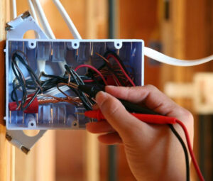
All multimeters will have a positive probe and common probe. The probes’ leads must be plugged into their appropriate inputs on the multimeter for accuracy.
Clamp-on Ammeter
The clamp-on ammeter is used to measure Amperage; Amperage is the electrical current flowing through a conductor. The clamps of the meter will sense the electrical fluctuations that are produced by the electrical current when clamped on a single conductor, giving a meter reading in Amps.
RMS vs True RMS Meter
When you use a multimeter to measure an AC voltage or Amperage, the reading on the meter is an “RMS” or “root mean square” reading. We sometimes call the RMS value the “effective value” of an AC voltage or Amperage. By that we mean that the RMS value of an AC voltage or Amperage has the same effect as a DC voltage or DC Amperage of the same value. Most inexpensive meters use an averaging technique to determine RMS.
True RMS instruments are preferred when working on modern circuits. When measuring the voltage or amperage of AC signals that are not pure sine waves, such as when you’re measuring the output of adjustable speed motor controls or adjustable heating controls, then you need a “true RMS” meter. A true RMS meter works by taking the square of the instantaneous value of the input voltage or current, averaging this value over time, and then displaying the square root of this average.
Meter Ratings
Multimeters aren’t a one-size-fits-all device. For example, the multimeter used to troubleshoot a problem with a computer or a radio won’t be appropriate for HVAC work. Multimeters are classed by rating:
- CAT I: isolated devices (like the radio mentioned above) or indoor, insulated, protected electronic devices
- CAT II: power tools, appliances, indoor residential outlets
- CAT III: industrial equipment, indoor electrical supply panels, appliance outlets near service entrances, HVAC equipment
- CAT IV: transformers, utility poles, well pump lines, HVAC units
Cat III and Cat IV meters are capable of measuring as much as 1000 volts, and are robust enough for these high-current, high-voltage circuits.
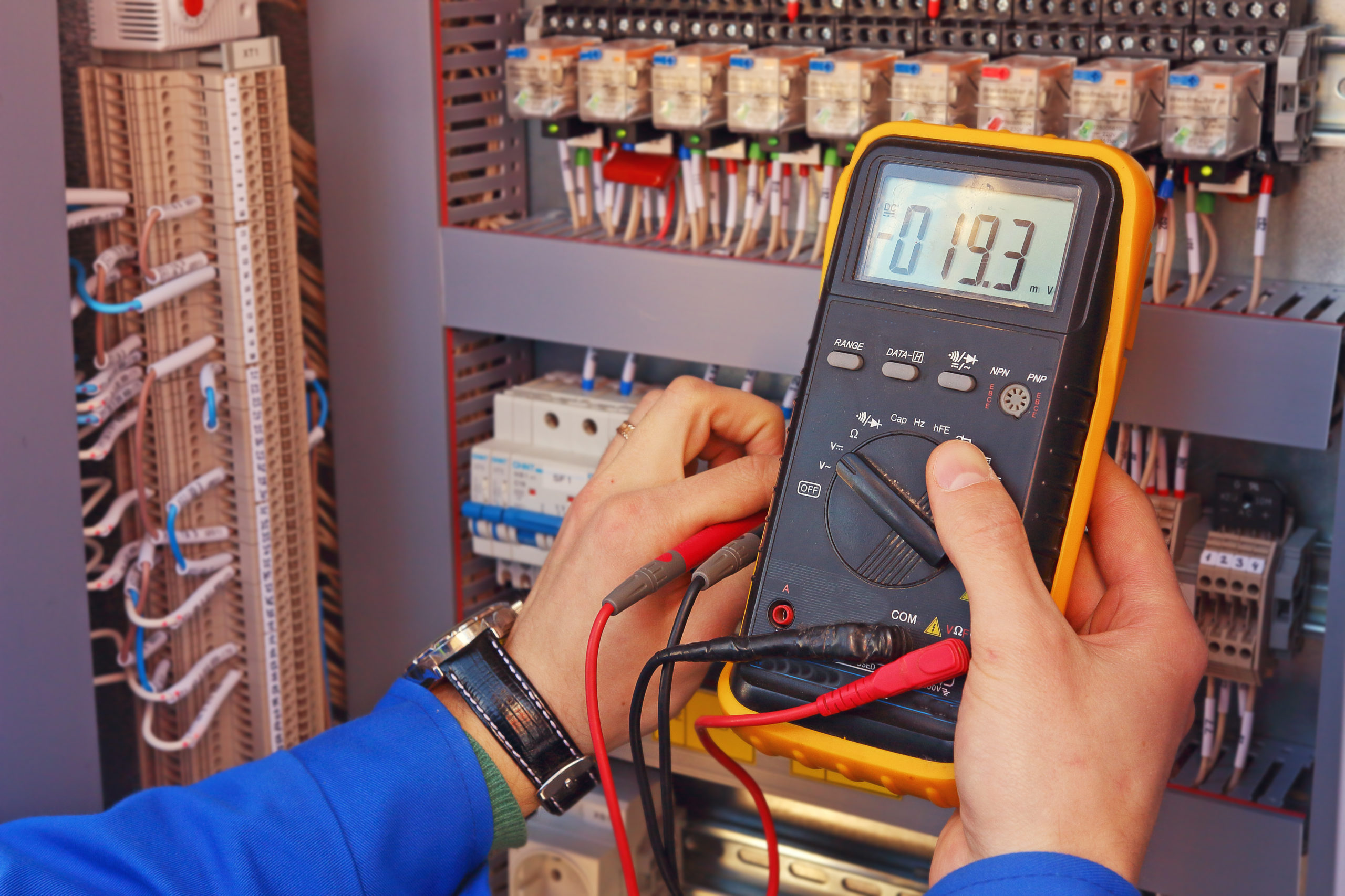
How to Measure Voltage With a Multimeter
- Plug the leads of the two probes into their appropriate inputs on the front of the multimeter.
- Turn the meter’s dial to AC voltage.
- Use the probes (or alligator clips) to measure voltage at the load, making sure the probes are making contact with the correct terminals.
When measuring DC voltage, ensure that the multimeter’s dial is turned to the DC voltage setting (on some multimeters, this might be on the meter’s secondary menu).
Additionally, the polarity must be correct; many newer multimeters have a polarity correction that can adjust for a correct reading if the probes are on the wrong terminals, but older ones may not. A reading with reversed polarity can be inaccurate.
How to Measure Resistance and Continuity
Measured in ohms, resistance is the degree to which electron flow is opposed in a circuit. You can expect resistance will be built into things like motor windings or a light bulb.
- Insert your probes’ leads into their respective jacks on the multimeter.
- Make sure that your meter is set for ohms (possibly on the secondary menu).
- Connect the probes to the terminals on the load and energize the circuit.
- Your meter should display the ohm or milliohm reading.
- A break in continuity (such as a broken winding in a motor) will read 0.L, or infinite resistance.
Measuring Amperage With a Clamp-On Ammeter
Before starting, the probes’ leads must be in their respective jacks on the front of the multimeter. There is a separate jack on the instrument that’s labeled for Amperage. It’s important to know that any Amperage that’s greater than 10 amps should be measured with a clamp-on ammeter and not probes.
- Turn the dial on the multimeter to Amperage.
- Make sure that the leads are connected to the load in series, protecting the multimeter itself; in other words, connect one lead to the switch and one to the load, making the multimeter part of the circuit itself.
- Turn on the switch and measure amperage.
When using a clamp-on ammeter, you can use a multiplier wrapped around the clamps, simply by taking a piece of wire and wrapping it around in 10 windings and then dividing the reading by 10. For example,if you are using a multiplier and your ammeter reads 1.5 amps, you can then divide that by 10 and arrive at 0.15 amps. This is useful in small, fractional amperage readings.
How to Test Diodes Using Your Multimeter
A diode can serve many functions in a circuit working as a rectifier that switches AC current to DC, signal limiters, voltage regulators, switches, modulators or oscillators. Across those functions, the diode has one property — it will only conduct electrical current (Amperage) in one direction.
A diode that’s installed properly is referred to as “forward biased,” while one that’s installed backward is “reverse biased” and will not conduct electric flow (Amperage). When testing diodes, the proper polarity for your probes is especially important.
- The diode’s positive lead is the anode, and the negative lead is the cathode.
- Plug the probes’ leads into the diode jack (clearly labeled) and the common jack.
- Turn the meter’s dial to Ω Ohms and click the ‘selector’ button for the secondary menu.
- Click the selector a second time for the -I>- Diode and you will see a V on the screen.
To check for a shorted diode, reverse the probes. The reading should be zero volts. A normal reading again would indicate a short. A failed diode would show a reading of zero regardless of how the leads are connected. It would indicate that the diode is not conducting current in either direction.
How to Measure Capacitance of a Capacitor Using a Multimeter
Capacitors are a passive device that stores electrical energy in a circuit Electrostatically. Its effect in the circuit is called capacitance; picture a rubber membrane in a pipe that won’t allow water to pass, but can stretch to allow more water to be stored behind it in the pipe.
- Plug your probes’ leads into their appropriate jacks on the multimeter.
- Turn the meter’s dial to the capacitor symbol.
- Discharge the capacitor using either a two-watt, 20k ohm bleed resistor across the terminals or a special capacitor discharge tool, otherwise, you risk an electric shock even if the circuit is turned off.
- Use your meter’s probes or clips on the terminals of the capacitor and your reading should show up as microfarads. In the case of a run capacitor, your reading should be plus/minus 10% of the capacitor’s rating (start capacitors are usually rated higher).
Be aware that in some HVAC units, you might encounter a dual capacitor that’s used to save space. A dual capacitor houses two separate capacitors in the same case; they will share the same common (ground) terminal, but with two separate hot terminals.
Using a Multimeter to Measure Temperature and Test Flame Signals in a Gas Furnace
The flame in a gas furnace conducts electricity itself. The flame and pilot are controlled by the IFC, a circuit board in the bottom of the unit. The flame envelops a sensor and a signal is passed through it, turning to DC current in the process; this is known as flame rectification. An insulated green wire from the burner then goes back to the IFC, informing it that the flame is present.
Flame signal is measured in microamps (a millionth of an amp) and is measured with the following steps:
- Plug your red lead into the jack marked for microamps/milliamps and the black lead into the common jack.
- Rotate the dial to the microamps setting, then go to the secondary menu to change this to DC microamps.
- Disconnect the flame sensor and connect the red lead to the wire supplying the sensor, with the black lead on the sensor. This will make the multimeter part of the circuit, connected in series.
- Fire the burners and look at the value on the multimeter.
A signal between one and eight microamps indicates a good sensor, but a problem with the IFC. A weaker reading would point toward a continuity test of the ground wire and resistance test of the sensor.
For more details on how to use a multimeter, as well as 3D simulations to walk you through real-life scenarios, check out Interplay Learning’s How to Use a Multimeter course.

Chad Soucy
Interplay Learning Electrical Expert
Chad is Interplay’s electrical expert and is a Master Electrician. Chad has progressed as an electrical professional throughout his career, with early beginnings in rewiring/wiring homes to QA/Commissioning plants, honing his skills in all aspects of the electrical trade along the way. He transitioned his career through Residential, Commercial and Industrial sites, and in 2012, further expanded on his mission to lifelong learning in becoming an electrical instructor. He continued on this path as an online course developer and is steadfastly committed to electrical safety and sound adult learning theories.